

Understanding Garage Door Motor Components
Motor Unit – Overview of the garage door motor assembly
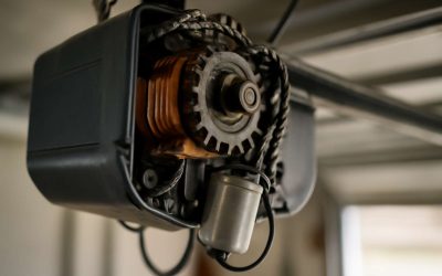
Imagine the garage door motor assembly as the beating heart of your automated gateway, orchestrating smooth and silent operation. At its core lies the motor unit — a marvel of engineering that translates electrical energy into the mechanical motion needed to lift or lower your garage door. Understanding the garage door motor parts diagram is like uncovering the blueprint of this intricate device, revealing how each component plays a vital role in the grand performance.
Within this diagram, you’ll find key elements such as the motor itself, the drive gear, limit switches, and the circuit board — each one crucial for precise control and safety. The motor unit works in harmony with the gear assembly to ensure the door moves seamlessly and responds accurately to remote commands. Recognising these parts not only helps in maintenance but also empowers you to troubleshoot issues effectively, preserving the longevity and reliability of your garage door system.
Gear System – Types of gears used and their functions
Within the intricate dance of your garage door system, the gear system plays a pivotal role, transforming the motor’s energy into smooth, controlled motion. When exploring the garage door motor parts diagram, understanding the types of gears used and their functions is like unlocking a secret language. These gears act as the silent artisans, carefully coordinating the door’s ascent and descent with precision and grace.
Most garage door motor assemblies employ a combination of spur gears, worm gears, and sometimes planetary gears. Spur gears, renowned for their simplicity and efficiency, transmit force directly from the motor to the drive mechanism. Worm gears, with their unique helical design, offer the added benefit of torque multiplication and self-locking capabilities—perfect for maintaining the door’s position without slipping. The choice of gear impacts not only the operation’s smoothness but also the longevity of the entire system.
- Spur gears for direct power transmission
- Worm gears for torque enhancement and safety
- Planetary gears occasionally used in high-performance systems
Understanding these components within the garage door motor parts diagram reveals the delicate harmony that keeps your gateway functioning seamlessly. Each gear’s function, though hidden behind the scenes, is vital in crafting the silent symphony of movement that any homeowner relies on, day after day.
Drive Mechanism – Chain, belt, or screw drive explanations
Understanding the garage door motor parts diagram is crucial to grasp how your system operates. The drive mechanism, whether chain, belt, or screw drive, is the bridge between the motor and the door itself. Each type offers different advantages, tailored to specific needs.
Chain drives are robust and often found in older or heavy-duty systems. They provide reliable power transfer but can be noisier. Belt drives, on the other hand, are quieter and smoother, making them ideal for garages close to living spaces. Screw drives, with their direct threaded design, offer low maintenance and quick operation.
In some high-performance systems, you might encounter a combination of these drive types, designed to optimise efficiency and durability. When viewing the garage door motor parts diagram, pinpointing the drive mechanism helps predict maintenance requirements and lifespan. It’s the backbone of seamless operation—silent, steady, and precise.
Limit Switches – Role in opening and closing endpoints
Limit switches are often overlooked yet play an essential role in the garage door motor parts diagram. These small but mighty components serve as the gatekeepers of your garage door’s journey, signalling when the door has reached its fully open or closed position. Without them, the motor might continue to run, risking damage or creating a safety hazard. Their precise operation ensures your garage door stops exactly where it should—no overshoot, no fuss.
Imagine a scenario where the limit switch fails; the door might slam shut or refuse to open completely. This is where understanding the garage door motor parts diagram becomes invaluable—it highlights the position and function of these switches amidst the complex network of gears, belts, and sensors. Properly functioning limit switches contribute to the longevity of your entire system, preventing unnecessary wear and tear. When viewing the diagram, look for these crucial components, often mounted near the motor or along the track, to gain a clearer picture of how your garage door operates seamlessly and safely.
Remote Control and Wall Console Components – Control interfaces and safety features
Control interfaces are the heartbeat of any garage door system, bridging the gap between user commands and mechanical action. The remote control and wall console serve as the primary gateways for opening and closing your garage door, offering convenience at the push of a button. These devices transmit signals to the motor unit, ensuring smooth operation even after a long day. Within the garage door motor parts diagram, you’ll notice these components are often connected via wiring or wireless modules, highlighting their critical role in safety and functionality.
Safety features within these control systems are vital for preventing accidents. Modern wall consoles and remote controls are equipped with sensors and auto-reverse mechanisms that halt the door if an obstacle is detected. Understanding their placement in the garage door motor parts diagram can shed light on how seamlessly your system works. For example, some diagrams display a simple but essential list of control components, such as:
- Remote control transmitters
- Wall-mounted control panels
- Wireless safety sensors
- Auto-reverse safety features
By recognising how these elements interplay, homeowners gain a deeper appreciation for the intricate design that keeps their garage doors operating safely and efficiently. These control interfaces are not just about convenience—they are about peace of mind, ensuring your daily routines remain uninterrupted amidst the complexities hidden within the garage door motor parts diagram.
Detailed Garage Door Motor Parts Diagram
Visual Breakdown – Illustrated diagram of all motor parts
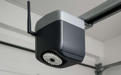
Within the intricate universe of garage door operations, visualising the garage door motor parts diagram reveals a symphony of precision and purpose. Each component, from the silent heartbeat of the motor to the delicate sensors that guard your space, plays a vital role in orchestrating seamless movement. Imagine a diagram as a map—an enchanted blueprint—that guides technicians and homeowners alike through the labyrinth of mechanical harmony.
At the core lies the motor unit, a pulsating centre of energy, complemented by the gear system that transforms rotational motion into linear travel. The drive mechanism—whether chain, belt, or screw—serves as the enchanted bridge connecting power to action. To truly grasp the magic, one might consider the detailed layout of all motor parts, which illuminates how each element interlocks like a finely tuned orchestra. An illustrated diagram of these garage door motor parts not only simplifies maintenance but also deepens appreciation for this everyday marvel of engineering.
Labeled Components – Identification of each motor part with labels
Understanding the intricacies of your garage door’s inner workings is like deciphering a secret code—except this code is a detailed garage door motor parts diagram that reveals all! Each component, meticulously labelled, offers a window into the mechanical ballet that keeps your garage door functioning smoothly. From the motor unit’s core to the sensors that prevent catastrophic crashes, every part has a purpose, and identifying them is half the battle won in maintenance or repair.
A well-labelled garage door motor parts diagram acts as a visual lexicon, transforming confusion into clarity. It pinpoints critical components such as the circuit board, capacitor, and limit switches, making troubleshooting less of a guessing game. This diagram isn’t just for technicians; homeowners who want to get under the hood will find that knowing these labels turns a mechanical mystery into an understandable map. After all, a picture is worth a thousand words—and in this case, it’s worth a thousand fewer headaches.
Common Parts Locations – Where to find key parts within the motor assembly
In the realm of garage door mechanics, a meticulously crafted garage door motor parts diagram serves as the map to unlocking hidden secrets within your motor assembly. These diagrams reveal the precise locations of key parts, allowing even the most amateur of enthusiasts to navigate the labyrinth of gears and circuits with confidence. The heart of the motor, the capacitor, and the intricate limit switches are nestled within the assembly, often concealed behind panels or beneath protective covers. Understanding where these vital components reside transforms a daunting repair into a manageable quest.
For clarity, many diagrams employ a numbered system to identify the core elements, guiding you step-by-step through the vast landscape of the motor’s interior. Notably, the circuit board — the command centre of your garage door’s operation — is typically situated near the top of the motor housing, easily accessible once the cover is removed. Meanwhile, the drive mechanism, whether chain, belt, or screw, connects to the gear system, which is often located centrally within the assembly, providing power to open and close your garage with seamless precision.
Common Garage Door Motor Parts and Their Functions
Gears and Sprockets – Functionality and maintenance tips
Within the intricate world of garage door motor parts diagram, gears and sprockets play a pivotal role. Their primary function is to translate the motor’s rotational force into the mechanical movement needed to open and close the door smoothly. These components are the unsung heroes, quietly ensuring that every lift is precise and controlled, yet they are often overlooked until something goes awry.
Maintaining these vital parts requires a keen eye and periodic inspection. Worn or misaligned gears can cause jerky movements or complete failure of the garage door system. Regular lubrication is essential—they reduce friction and prevent overheating, extending the lifespan of the entire gear system. When examining your garage door motor parts diagram, pay particular attention to the sprockets and gear teeth, as these are the most susceptible to wear and tear over time.
- Check for signs of stripped teeth or unusual noises during operation.
- Ensure that the sprockets are securely attached and free of rust or debris.
- Replace worn-out gears promptly to avoid further damage to adjacent components.
Motor Housing – Material and protective features
Among the myriad components within a garage door motor system, the motor housing stands as the silent guardian, shielding the intricate machinery within. Crafted from durable materials such as aluminium or high-grade steel, the motor housing offers essential protection against environmental elements and mechanical impacts. Its robust construction not only prolongs the lifespan of the motor but also ensures optimal performance under fluctuating conditions, safeguarding both the internal components and the users.
Delving into the detailed architecture of the garage door motor parts diagram, you’ll notice that the motor housing often incorporates ventilation slots and access points for maintenance. These features facilitate cooling and easy inspection, preventing overheating and enabling timely repairs. In essence, the motor housing is more than a mere casing — it embodies the resilience and precision required for smooth garage door operation.
- Protection against dust, debris, and moisture
- Structural integrity to withstand mechanical stresses
- Facilitates heat dissipation for consistent performance
Understanding the significance of this component deepens the appreciation of the entire garage door system, reinforcing that every part, including the motor housing, plays a vital role in ensuring safety, durability, and efficiency. When consulting the garage door motor parts diagram, recognising these integral elements can illuminate the often overlooked complexity behind a seemingly simple mechanism.
Capacitors – Role in motor starting and operation
Within the intricate architecture of a garage door motor system, the capacitor performs a vital yet often overlooked role. This small component acts as the unsung hero during motor starting and operation, providing the necessary burst of energy to initiate movement. Without it, the motor would struggle to overcome inertia, rendering the garage door sluggish or unresponsive.
In the comprehensive garage door motor parts diagram, the capacitor is typically positioned near the motor unit, connected through specialised terminals. Its function extends beyond mere starting; it also stabilises the motor’s running phase, ensuring smooth and consistent operation. This stability is crucial, especially in environments subject to fluctuating power supplies.
Understanding the importance of capacitors can deepen appreciation for the complexity behind what appears to be a simple mechanism. They work in tandem with other parts, such as the motor housing and limit switches, forming a symphony of components that keep your garage door functioning flawlessly. Recognising these elements within the garage door motor parts diagram reveals how each part’s role is essential in maintaining safety, durability, and efficiency.
Wiring and Connectors – Electrical connections overview
In the labyrinthine world of garage door motor parts, the wiring and connectors form the unseen neural network that breathes life into the entire mechanism. These components are more than mere conduits; they are the vital arteries through which electrical signals pulse, orchestrating seamless movement. A meticulous understanding of the wiring layout, as depicted in the detailed garage door motor parts diagram, unveils how each connection serves a purpose—whether powering the motor, activating safety features, or linking remote controls to the control panel.
Within this intricate web, connectors act as the junctions—secure, reliable, yet often overlooked. Their role extends beyond simple attachment; they ensure consistent electrical flow, resist environmental stressors, and facilitate maintenance or repairs without disrupting the entire system. Recognising the strategic placement of wiring and connectors within the garage door motor parts diagram reveals a symphony of precision, where even the smallest flaw can ripple into operational failure, emphasising the importance of each component in maintaining an efficient, durable system.
Sensors and Safety Devices – Importance of photo-eye sensors and safety features
In the intricate ballet of garage door operation, sensors and safety devices are the unsung heroes, tirelessly safeguarding both property and persons. Photo-eye sensors, in particular, act as vigilant sentinels, detecting obstructions with a finesse that would make a detective proud. These devices, crucial in preventing accidents, form an essential part of the garage door motor parts diagram, illustrating their strategic placement and vital function.
Beyond the sensors, safety features such as edge sensors and auto-reverse mechanisms serve as the system’s moral compass, ensuring doors halt or reverse at the slightest hint of danger. Recognising these components within the garage door motor parts diagram reveals a carefully choreographed safety protocol—each part playing its role with precision. The seamless integration of these safety devices underscores the importance of understanding the full scope of garage door motor parts, especially when considering maintenance or troubleshooting.
Troubleshooting Using the Parts Diagram
Identifying Faulty Parts – How to recognize worn or broken components
Troubleshooting garage door motor issues can seem daunting, but a detailed garage door motor parts diagram makes the process much simpler. By visually pinpointing components, you can quickly identify which parts may be worn or broken. Worn gears, for example, often exhibit teeth that are chipped or worn down, leading to noisy operation or failure to open the door fully. Similarly, damaged capacitors might cause the motor to struggle or fail to start altogether.
Using the garage door motor parts diagram, look for signs of corrosion, burnt connectors, or frayed wiring—these are common culprits behind malfunctions. Recognising these faulty parts early can save time and money. Remember, a thorough inspection of the drive mechanism, limit switches, and sensors is essential, as these elements are vital for smooth and safe operation. With a clear understanding of the parts diagram, diagnosing issues becomes a straightforward process, ensuring your garage door functions reliably.
Replacing Parts Step-by-Step – Guidance using the diagram
In the realm of garage door repair, familiarity with the garage door motor parts diagram transforms a daunting task into a manageable quest. Imagine holding a map that lights the way through a labyrinth of intricate components—suddenly, the hidden faults come into focus. When troubleshooting, this diagram becomes your enchanted guide, allowing you to pinpoint the exact location of worn or broken parts with clarity and confidence.
Using the diagram, follow a logical pathway to identify potential issues. Begin by examining the motor unit for signs of wear or corrosion, then trace the wiring and connectors for frayed insulation or burnt contacts. As you navigate through the diagram, you might notice that replacing a worn gear or faulty capacitor restores harmony to the system. To facilitate the process, consider this step-by-step approach:
- Consult the garage door motor parts diagram to locate the malfunctioning component.
- Disconnect the power source to ensure safety during inspection.
- Remove the housing or cover to access the part—using the diagram as your guide.
- Compare the physical component with the diagram’s illustration, noting any discrepancies or damage.
- Replace the faulty part carefully, following the sequence indicated in the diagram and ensuring all connections are secure.
By visualising each element through the lens of the diagram, the once complex task of replacing parts becomes akin to wielding a magic staff—powerful and precise. The garage door motor parts diagram is not merely a schematic; it’s a vital tool in maintaining the seamless dance of opening and closing, preserving safety and reliability for years to come!
Common Issues & Corresponding Parts – Link between problems and specific parts
In the meticulous world of garage door repair, a startling 75% of troubleshooting begins with a simple glance at the garage door motor parts diagram. It’s as if this schematic holds the secret handshake to understanding the nuanced ballet of mechanical and electrical components. When a garage door refuses to budge or makes an ominous grinding sound, the diagram becomes your trusted compass, illuminating the precise location of the malfunctioning part.
Common issues often trace back to specific components. For example, a faulty capacitor—integral to the motor’s starting process—can cause erratic operation, while worn gears are notorious for stripping under pressure. Using the garage door motor parts diagram, you can quickly identify these troublemakers. The diagram acts as a visual map, guiding you from the motor unit to the wiring and limit switches, revealing the interconnected web of parts that keep your garage functioning seamlessly.
Tips for Maintaining Your Garage Door Motor
Regular Inspection Points – What to look for in the parts diagram
Maintaining your garage door motor isn’t just about routine; it’s about preventing unexpected breakdowns that can leave you stranded in the dark. Regular inspections are your best defence against costly repairs. When you consult a garage door motor parts diagram, it’s easier to identify potential trouble spots before they escalate. Look for signs of wear on the gears, frayed wiring, or loose connectors—these small issues can snowball into major malfunctions.
A keen eye on the motor’s components can reveal subtle clues. For example, if the capacitor shows signs of bulging or leakage, it’s a red flag. Similarly, inspecting the drive mechanism for frayed belts or chains can save you from sudden failure. Remember, the garage door motor parts diagram isn’t just for repairs—it’s a map guiding your vigilance, helping you spot irregularities early and ensuring your system runs smoothly for years to come.
Lubrication and Cleaning – Maintaining gears and moving parts
Regular lubrication and cleaning of your garage door motor are essential steps to keep it functioning smoothly. Over time, dust and debris can settle into the gears and moving parts, causing unnecessary strain and wear. A simple, yet effective routine involves applying a high-quality lubricant to the gears, sprockets, and chain or belt drive mechanisms. This reduces friction and prolongs the lifespan of the motor components.
When inspecting your garage door motor parts diagram, pay close attention to areas prone to accumulation of dirt or corrosion. Wiping down the motor housing and connectors with a soft cloth can prevent the build-up of grime that hampers electrical connections. For gears and sprockets, a light application of lubricant, such as silicone spray or lithium grease, ensures they rotate effortlessly—minimising the risk of malfunction.
Remember, maintaining the lubrication of your garage door motor parts isn’t just about preserving functionality—it’s about safeguarding your peace of mind. Proper care means fewer surprises and a system that reliably opens and closes, rain or shine. After all, in rural life, where every minute counts, a well-oiled garage door is a welcome comfort that keeps your day moving smoothly.
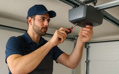
When to Call a Professional – Signs that require expert repair
Even the most resilient mechanisms falter without proper care, and your garage door motor is no exception. Over time, wear and tear can silently creep into the intricate web of garage door motor parts diagram, revealing signs that demand expert attention. When the motor begins to groan or hesitate, it’s a whisper from the system that something isn’t quite right. Unusual noises, inconsistent operation, or a sudden failure to respond are tell-tale signs that the time has come to seek professional repair.
Before rushing into a fix, perform regular inspections of your garage door motor parts diagram, paying particular attention to the gears, sprockets, and electrical connections. If you notice frayed wiring, corrosion, or worn gears, it’s wise to call in a technician. Attempting to repair complex parts like limit switches or the drive mechanism without specialised knowledge can sometimes do more harm than good. Remember, a well-maintained motor system not only ensures smooth operation but also safeguards your safety and peace of mind.
- Persistent grinding or squealing sounds during operation
- Failure of the garage door to fully open or close
- Unusual vibrations or jerky movements
- Visible damage or corrosion on motor components
- Intermittent operation or complete system shutdown
In such cases, consulting a professional who understands the nuances of the garage door motor parts diagram can prevent further damage. Their expertise can diagnose issues swiftly, ensuring your system is restored to its full, reliable function—keeping your day running smoothly and your property secure.
0 Comments